JBtek 8 Channel DC 5V Relay Module for Arduino Raspberry Pi DSP AVR PIC ARM


Key features
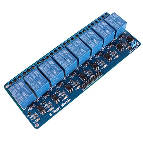
- •5V 8-Channel Relay interface board, and each one needs 15-20mA Driver Current
- •Equiped with high-current relay, AC250V 10A ; DC30V 10A
- •Standard interface that can be controlled directly by microcontroller (Arduino , 8051, AVR, PIC, DSP, ARM, ARM, MSP430, TTL logic)
- •Indication LED's for Relay output status
BrandJBtek
CategoryComputer Components
JBtek 8 Channel DC 5V Relay Module for Arduino Raspberry Pi DSP AVR PIC ARM
List Price: $17.42$15.68DEALYou Save: $1.74 (10%)
Free shippingFree Returns – 30 daysFree Order CancellationSecure Payment2–3 Days DeliveryGet It June 23, 2026In Stock (1)No marketing spamNo account requiredFulfilment by FedEx / Amazon / UPS / ShipwirePayPal / Card Buyer Protection
Customer Reviews
Reviews sourced from verified Amazon purchasers4.4
out of 5
Based on 10 reviews
5★
90%
4★
0%
3★
0%
2★
0%
1★
10%
Dirty crap with bad soldering joints!
Amazon Customer•November 9, 2017
First of all the reley board was very very dirty when I received it. Just like if somebody used it as a plate for eating something!
When I started using it in my projects several months ago (unfortunately, so I cannot try to get refund), I found out that 2 out of 8 releys are not working! The red light is turning on but reley never switches the state for those 2 releys! The other 6 works fine. This is a crap, very disappointed. Now I have to buy new module and wait for it to be shipped!.
After spending some time on debugging the board (i.e testing resistors and transistors), I tried adding more solder in soldering joints / add heat for non working releys, which fixed the issue. So apparently soldering was poor!. Hope this might be helpful for others who is in similar situation!
Clacky, but awesome switching for an Arduino (or other real time processor)
Kaleberg•May 27, 2017
This is an array of eight little relays capable of controlling AC or DC current and perfect for small battery projects as well as for use with 110V or 220V line current. (Check the specifications and your comfort level if you are planning to control higher voltages though.) Each relay is controlled by a single line from the Arduino and has connectors for normally open or normally closed. The board also needs a ground and 5V VCC hookup. These can come from the Arduino. (I don't know if they'll work with 3.3V logic levels, probably not.)
I've been using this array to control AC electroluminescent (EL) wires, and they work well. They are a bit noisy, but the relay clacking sound effects are what I want for the project. So far, I've only tested the relays with a 100ms delay, and they work fine. Since they are mechanical, I assume that there is some top speed. If you want to do 5ms switching, odds are you should get a board with TRIACs like the Sparkfun EL Sequencer or roll your own.
I've been using this array to control AC electroluminescent (EL) wires, and they work well. They are a bit noisy, but the relay clacking sound effects are what I want for the project. So far, I've only tested the relays with a 100ms delay, and they work fine. Since they are mechanical, I assume that there is some top speed. If you want to do 5ms switching, odds are you should get a board with TRIACs like the Sparkfun EL Sequencer or roll your own.
Works great, good value, hope you like clicky things :)
Stretch•November 12, 2016
Worked fine out of the box. I am using on a Pi 3 and the relay module seems stable and reliable using just the +5 and GND from the Pi. The relays are mechanical, and not silent. For my purposes (experimenting and prototyping) the ability to hear each one trip is helpful (I *know* the code executed when I hear it), and I really consider this a surprisingly good deal.
Make sure you have 10 M-F jumper cables if you're connecting to a breadboard (8 relays, 1 +5vdc, 1 gnd)
Also - this is an unmounted PC board. Make sure you do not leave anything conductive under it. (a sheet of paper is fine while experimenting, but you'll want to mount this properly before running current through the business end of the relays!)
Works great with Raspberry Pi and Falcon Player Plus!
TH•August 6, 2016
Works perfectly with Raspberry Pi3!! The logic circuits are 3.3v so it can be directly connected to the GPIO outputs! I am using an external 5v power supply to feed the relays as the RasClock takes up the 5v outputs on my Pi header. This board does include a jumper on the power header that I imagine is to jump the 3.3v from the Pi to the 5v input to drive the relays but I have not tried this so can't say if 3.3v is enough to drive the 5v relays (nor of the current draw would be too much for the Pi under that setup).
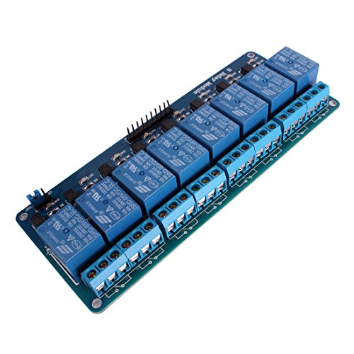
Pin outs:
Main header:
- GND - Pi ground
- VCC - Pi 3.3v
- 1-8 - Pi GPIO outputs
Power header:
- JD-VCC - 5 volts in for relay power
- GND - relay ground (this is tied to GND on the main header as well)
- VCC - 3.3v in/out (this is tied to VCC on the main header and carries 3.3v to power the logic circuits).
Mechanical Relays work awesome!
Robert Rael•December 31, 2015
I was a little worried that this would not work as great as the Sainsmart Relay that everyone talks about, but I used this with my Christmas Light Show (lightshowpi.org) and it works great. They are loud, but they are mechanical relays. I knew what I was getting into. I am glad they can handle 10 amps each so I can do long runs of LED Christmas lights on each channel. If you are in the market for mechanical relays for your Raspberry Pi, I highly recommend these.
The only thing you might dislike is that the power and negative are pins instead of screw on connectors. Very minor though, as I bought the female to female jumpers to connect to the GPIO pins on the Raspberry Pi.
The only thing you might dislike is that the power and negative are pins instead of screw on connectors. Very minor though, as I bought the female to female jumpers to connect to the GPIO pins on the Raspberry Pi.
Page 1 of 2


