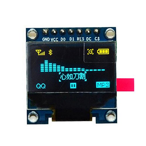
HiLetgo 0.96" SPI Serial 128X64 OLED LCD Display SSD1306 for 51 STM32 Arduino Font Color Yellow and Blue

Key features
- •0.96" SSD1306 128X64 OLED LCD Display with SPI Serial
- •Drive Duty: 1/64 Duty
- •Font Color: Yellow and Blue
- •Panel Size: 26.70mm x 19.26mm x 1.85mm
- •High resolution: 128 * 64
HiLetgo 0.96" SPI Serial 128X64 OLED LCD Display SSD1306 for 51 STM32 Arduino Font Color Yellow and Blue
List Price: $14.53$13.08DEALYou Save: $1.45 (10%)
Free shippingFree Returns – 30 daysFree Order CancellationSecure Payment2–3 Days DeliveryGet It June 24, 2026In Stock (1)No marketing spamNo account requiredFulfilment by FedEx / Amazon / UPS / ShipwirePayPal / Card Buyer Protection
Customer Reviews
Reviews sourced from verified Amazon purchasers4.5
out of 5
Based on 10 reviews
5★
70%
4★
20%
3★
0%
2★
10%
1★
0%
Watch out for bottom two corners, good post sales support from company.
Rahul Tikoo✓ Verified Purchase•April 24, 2018
The bottom corners have no under supports, so the screen cracks with very little pressure. The rest of it seems fairly sturdy enough. Note, once a bottom corner cracks the screen loses resolution and some lines are missing (interlaced lines).
Updated (4/30): Moved to 4 stars after quick support response and refund. I had already ordered 2 more and plan to add super glue underneath for added support.
Updated (4/30): Moved to 4 stars after quick support response and refund. I had already ordered 2 more and plan to add super glue underneath for added support.
Great little display
DCFusor✓ Verified Purchase•March 29, 2018
These are a sweet match for ESP processors used as "leaves" in my LAN of things. It's real nice to have a local display on them if you happen to be nearby or need to troubleshoot something. They just work...the only downside is that one of these, and odd sensor or two, and an ESP 8266 combined don't use enough power to keep the average USB power pack turned on - it's detected as "no load"!
Good if you can find the datasheet.
Brandon Davidson✓ Verified Purchase•January 14, 2018
Four stars for being cheap. Almost gave it three for the absolute lack of documentation, but you can figure out most of it if you dig up the manufacturer's datasheet on Google. Here's what you need to know:
GND: Ground.
VCC: Power supply for panel driving voltage.
D0~D7: These are 8-bit bi-directional data bus to be connected to the microprocessor's data bus.
When serial interface mode is selected, D0(SCLK) will be the serial clock input, D1(SDIN) will be the serial data input, D2 should be left opened.
When I2C mode is selected, D1(SDA in) AND D2(SDA out) should be tied together; D0(SCL) is the I2C clock input
RES: This pin is reset signal input. When the pin is pulled LOW, initialization of the chip is executed. Keep this pin HIGH (i.e. connect to VDD) during normal operation.
DC: This is DATA/COMMAND control pin. When it is Pulled HIGH, the data at D[0~7] is treated as data. When it is pulled LOW, the data at D[0~7] will be transferred to the command register.
In I2C mode, this pin acts as SA0 for slave address select.
(Not used for serial mode)
CS: This pin is the chip select input. (Active LOW)
In I2C mode, it can be accessed at 0x3C, unless you pull up DC in which case it uses 0x3D. This board only has two of the data pins exposed, so it CANNOT be used in parallel mode. If you're handy with a soldering iron, you can probably switch it between I2C and SPI modes by moving resistors around, but I personally wouldn't risk it.
D0 D1 explained
techfan✓ Verified Purchase•January 11, 2018
I liked these, but it took a while to understand the connections.
I'm using an Arduino Pro Micro, and on advice from another reviewer, the u8g2 library.
You can pull this in from the libraries manager in arduino 1.8.5
The thing I wish was silk-screened informatively were the names for clock and data:
D0=clock
D1=data
I un-commented this line to choose the SSD1306 and used these values:
U8X8_SSD1306_128X64_NONAME_4W_SW_SPI u8x8(/* clock=A2*/ 20, /* data=A3*/ 21, /* cs=A10*/ 10, /* dc=A0*/ 18, /* reset=A1*/ 19);
Good!
Frank W.✓ Verified Purchase•January 3, 2018
I couldn't get this to work with Adafruit library and gave it two stars. HiLetgo contacted me and suggested the U8G2 library, which I tried and it works fine.
In the Arduino sketch you have to UNCOMMENT one constructor out of a list of about 100. I used this one:
U8G2_SSD1306_128X64_NONAME_F_SW_I2C u8g2(U8G2_R0,SCL,SDA,U8X8_PIN_NONE);
and the OLED works fine
In the Arduino sketch you have to UNCOMMENT one constructor out of a list of about 100. I used this one:
U8G2_SSD1306_128X64_NONAME_F_SW_I2C u8g2(U8G2_R0,SCL,SDA,U8X8_PIN_NONE);
and the OLED works fine
Page 1 of 2